

Appearance
Where the leads go
On the board, two markers show the leads:
- The red lead: a red ring with a + tag, labelled with its point.
- The black lead: a black disc with a light ring and a − tag, labelled with its point.
The point being measured pulses gently, and its net is lit across the board. The view zooms to keep both markers in sight.
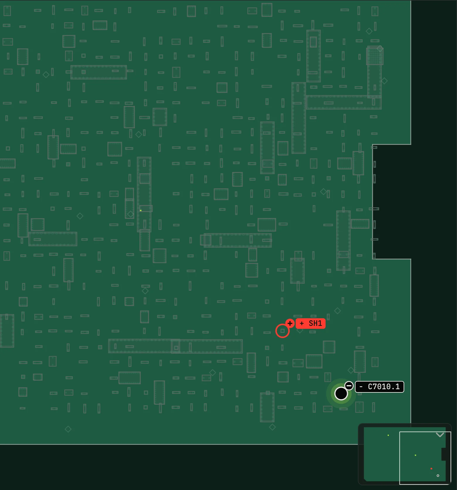
Which lead sits on ground depends on the mode, and NextProbe follows the way reference values are published so your readings compare with forums, videos and other techs' notes:
| Mode | Black lead | Red lead |
|---|---|---|
| DC voltage | Ground | The point |
| Diode mode | The point | Ground |
| Resistance to ground | The point | Ground |
Diode mode with red on ground and black on the point is the usual way diode readings are quoted for board repair. A reversed diode reading (black on ground) is sometimes used to compare with a good board; such a step says it is reversed. A step that came from a forum post or a video keeps the leads exactly as its source had them, and says "not stated" if the source didn't say.
When NextProbe chooses the pad itself, it picks one you can reach: a test pad before a tiny capacitor, the pad with the most room around it, and ground on a shield clip or screw pad on the same face.